LET US HELP YOU WITH YOUR TEST EQUIPMENT NEEDS.
We reply within 4 business hours (AEST). If we do not, you will receive $100 off your next purchase.
We reply within 4 business hours (AEST). If we do not, you will receive $100 off your next purchase.


We offer you advice that is gained from many years of assisting people from all industries with their individual requirements, technical objectives and challenges.
The Ametek stable of brands the are industry's greatest innovators, always being the first to release new technologies & features.
We work hard to ensure that you are very happy with every aspect your new test equipment solution and provide the most attentive after-sales care in the industry.
Talk to an expert today.
Our friendly team of highly trained specialists will quickly assist you.
We promise to respond within 4 business hours (AEST).
Or you will receive $100 off your next purchase. Read how it works.


Electrostatic discharge (ESD) is the sudden flow of electricity between two electrically charged objects caused by contact, an electrical short, or dielectric breakdown. A buildup of static electricity can be caused by turbocharging or by electrostatic induction.
Simulates electrostatic discharge events directly to the product, or to a nearby conductive surface.
Test Method
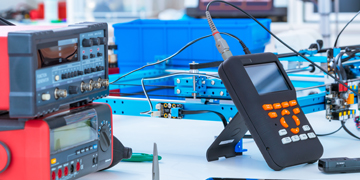
The ESD test requires that discharges be made to all exposed surfaces of the EUT, including connector back shells. Contact discharge is to the conducting surfaces of the product and air gap discharges are to non-conducting surfaces. The test also requires that contact discharges be made to a horizontal reference plane and vertical reference plane at locations 10cm from the front, rear and sides of the EUT. The ESD Simulators/Generators/Guns can be used for ESD Testing.
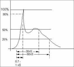
Typical rise time of the ESD pulse waveform is approximately 0.7 - 1nS with a hold time of 30 - 60 nS. (See image)
The test simulates ESD events that occur when the user touches the equipment under test or nearby metallic objects (e.g. filing cabinets). The test levels for both the heavy industrial and light industrial/commercial/residential standards are ±2kV and ±4kV for the contact discharge method and ±2kV, ±4kV, and ±8kV for the air gap discharge method.
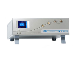
A transient event is a short-lived burst of energy in a system caused by a sudden change of state. The source of the transient energy may be an internal event or a nearby event. The energy then couples to other parts of the system, typically appearing as a short burst of oscillation.
In electrical and electronic engineering such electromagnetic pulses (EMP) occur internally as the result of the operation of switching devices. Engineers use voltage regulators and surge protectors to prevent transients in electricity from affecting delicate equipment. External sources include lightning (LEMP), electrostatic discharge (ESD) and nuclear EMP (NEMP).
Within Electromagnetic compatibility testing, transients are deliberately administered to electronic equipment for testing their performance and resilience to transient interference. Many such tests administer the induced fast transient oscillation directly, in the form of a damped sine wave, rather than attempt to reproduce the original source. International standards define the magnitude and methods used to apply them.
Simulates high frequency electrical disturbance on power and signal lines due to the switching of inductive loads on the AC line.
Test Method
The test waveform consists of a 15ms burst of pulses at 300ms intervals. The pulses have a rise time of 5ns and a dwell time of 50ns, with a repetition rate of 5 kHz.
For heavy industrial equipment the test levels are:
Noise is directly injected onto power lines through a capacitor and capacitive coupled onto I/O lines using a coupling trench. DC power ports connected to an AC-DC power adapter are not tested.
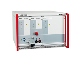
Surges, or transients, are brief overvoltage spikes or disturbances on a power waveform that can damage, degrade, or destroy electronic equipment within any home, commercial building, industrial, or manufacturing facility. Transients can reach amplitudes of tens of thousands of volts.
Simulates low frequency, high-energy electrical transients on power lines and long distance I/O lines (such as telephone lines) coupled from nearby lightning strikes.
Test Method
Test is applied to AC and DC power ports. The open circuit signal wave-shape has as 1.2µs rise time and 50µs hold time. Surges are applied in common mode (line-to-ground) and in differential mode (line-to-line). All surges are synchronized to the 0°, 90°, 180° and 270° phase angles of the AC voltage. DC power ports are not tested if they are connected to an AC-DC power adapter, in which case the AC-DC adapter should be submitted for testing.
Test levels for the residential, commercial and light industrial generic standard are 2kV common mode and 1kV differential mode on AC power lines. For DC power lines, the test levels are 0.5kV for both differential and common mode. Although the test is not currently required for the heavy industrial generic standard, it suggests test levels of 4kV common mode and 2kV differential mode.
Simulates brown outs and blackouts on AC power lines.
Test Method
This test is applied to AC power ports rated at less than 16 amps per phase. All voltage shifts are synchronized to the zero crossing of the AC voltage.
Typical test levels for the generic light industrial standard involve a 30 percent dip in the line voltage for 10ms, 60 percent dip for 100ms and dropout for 5000ms. There are currently no requirements for Heavy Industrial equipment.
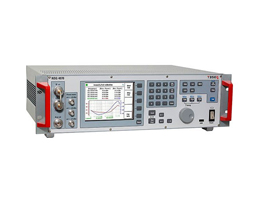
All linear amplifier systems, when given a sufficiently strong input signal, will reach a point where the system departs from a linear relationship between input and output. At this point the system is said to be going into compression or beginning to saturate. Beyond this point, the linear relationship between input and output is no longer valid and the amplifier is no longer considered to be linear. An internationally recognised figure of merit, used for defining the extent of linearity of an amplifier, is the 1dB compression point. This is the point of –1dB departure from linearity. The output power of an amplifier cannot increase indefinitely and when an increase in input power generates no discernible increase in output power, the amplifier is said to be saturated, and by definition the output is not proportional to the input signal. This point is often referred to as Psat on a datasheet or sometimes P3dB. Generally, saturated power is of importance when considering the pulsed power requirements in something like automotive testing while linear power is of importance when considering the AM (amplitude modulation) waveform used in commercial EMC testing.

Thank you for helping our team select the correct product to facilitate testing to the various required standards. Our lab is now equipped with a range of Teseq, IFI and Milmega products and the entire solution fulfils our testing requirements. We really appreciate your technical advice & support.
Scott Emerson
EMC TEST ENGINEER

Aside from receiving information when we need to upgrade or purchase an item of test equipment, what we really need from an equipment partner is advice based on industry experience. Thank you for the many hours spent talking to us and answering our questions. This level of customer care is rare in this industry.
Janet Boyle
EMC TEST ENGINEER TEAM LEADER

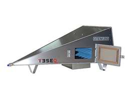
The Teseq GTEM is a great testing tool to have. We are now performing all pre-compliance testing in-house and saving lots of money which we were spending earlier with test labs. It has given us significant more testing capability and flexibility. Thank you for your help.
Sue Benton
TECHNICAL DIRECTOR
Our experts are all pre-eminent leaders in electrical products who provide excellent support in their areas of expertise.
Technical supportOur friendly team are highly trained product experts who really enjoy helping customers find what they need.
call 1300 387 326We promise to respond within 4 business hours (AEST) or you will receive $100 off your next purchase.
Enquire now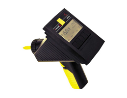
-259x200.jpg)
-259x200.jpg)
-259x200.jpg)