Power Factor Correction

Power Factor Correction

What is power factor?

Power factor is an expression of energy efficiency and is a measure of how effectively incoming power is used in your electrical system. It expresses the ratio of real power actually used in a circuit to the apparent power delivered to the circuit and is usually expressed as a number between 0 and 1. The higher the power factor, the more proportion of your supplied power is being used for useful work and the more efficient your site is at utilising the supplied power.

It’s important because you may be paying for power that you cannot use to power your equipment. Improving your power factor results in less current being drawn, less heat and greater longevity of your electrical system. Improving your power factor may also result in significant savings on your electricity costs.

Learn more about Power Factor

Why Resonance is a Problem in Power Factor Correction Systems

Brochure

Sinexcel SVG P5 Graphic

ARE YOU PAYING FOR ELECTRICITY THAT YOU ARE NOT USING?

Improving your power factor can result in considerable savings on your power bills. For example, think of a glass of beer, made up of the thirst-quenching liquid and the froth.

The drinkable liquid represents Real Power, the power that performs the actual work. Think of this as the satisfying liquid in the beer you’ve paid good money to drink. The froth represents Reactive Power, the power that energises your equipment. It doesn't do any useful work – it doesn’t quench your thirst.

As you pay for the whole glass of beer, you want more of the liquid and less of the froth to get value for money. Poor power factor is like a beer with too much froth, with the froth representing wasted energy (money). By improving your power factor, most or all of the power supplied that you are paying for is being used for productive work. By not paying for the froth, you save money.

Case Study showing cost-saving

Brochure

SAVING MONEY BY IMPROVING POWER FACTOR

The Electricity Utilities and Retailers are changing the way they bill you.

Traditionally, our electricity has been charged according to a kW (kilowatt) demand tariff which is commonly known as ‘real power’. This means that you are charged for the electricity that you actually use. The change is that you will now be charged according to a kVA (kilovolt-ampere) demand tariff which is commonly known as ‘apparent power’ (or real power plus re-active power).  Every electrical facility consumes an amount of re-active power. This energy is considered ‘wasted’ as it does not perform useful work. The changes are currently being rolled out across Australia.

Improving your power factor can result in considerable savings on your power bills.

By installing Power Factor Correction equipment, you will be able to reduce your Peak kVA Demand Tariff and this will result in significant savings in your electricity bill.

Reducing your electricity costs with Power Factor Correction

How can Fuseco help you?

Fuseco is Australia's leading experts in Power Factor Correction. Contact us for a free site appraisal and no obligation assessment to see if you can save money on your energy costs.

We welcome you to contact us and tell us about your site. We will happily assess your bill and determine whether you need Power Factor Correction.

If you do, we will offer a tailored solution and show you how much you will save. We will also clearly explain your Return On Investment (ROI) so you can make an informed decision.

There’s no charge - no obligation.

Sinexcel SVG P5 100kVAr Wall Mount


THE SINEXCEL SVG

Simple power factor correction solutions incorporate banks of capacitors that work as silent reactive power ‘generators’. These systems were designed many decades ago when electrical environments were a lot simpler than they are today. They are common, very economical and suitable for linear load environments.

However, in today’s modern electrical environments, linear loads are not easy to find. Due to the proliferation of LED/energy efficient lighting, switch-mode power supplies, VSD’s, UPS’s, servers/computers and typical appliances, today’s electrical systems experience complex, dynamic non-linear loads. Loads are being switched so fast that the traditional capacitor bank PFC systems struggle to maintain an effective compensation set-point. Therefore, they are perpetually ‘chasing’ the load, either under or over-compensating but rarely providing effective compensation.

Fuseco offers the latest generation of advanced performance PFC solutions that offer instantaneous, dynamic step-less compensation, ideal for the challenging demands of modern electrical environments. The Sinexcel SVG solutions do not need a capacitor bank and offer many advantages due to their compact & modular configuration (including wall-mount options).

Learn more about the 200kVAR Wall Mounted PFC Solution 

Features

  • SiC Technology

Sinexcel are the first Power Factor Correction manufacturer to implement Silicon Carbide Mosfet (SiC) technology, allowing the switching frequency to be increased up to 4.5 times the present standard of 20kHz. This has a dramatic impact on ventilation and sizing of supporting components.


  • Exceptional performance

Can maintain a Power Factor of 0.99 lagging or unity if required.


  • Dynamic step-less compensation

The Sinexcel SVG profiles the load and operates with a response speed of <15ms (Dynamic reaction time is less than 50us). It is a virtual real-time instantaneous response and it only injects the kVAr that is required in that moment. Therefore, the SVG is never over-compensating or under-compensating.


  • Wall mounted modules can be parallel connected

Wall mounted Sinexcel SVG modules can be parallel connected to increase capacity in a 'Master / Master / Master' arrangement. In the event that one unit shuts down, the other units remain operational.


  • Corrects lagging (inductive loads) AND leading (capacitive loads) 

Power factor range (-1 to +1)


  • Can work with & enhance existing capacitor bank systems

If you already have an existing capacitor bank PFC system, you can add an SVG to improve the performance achieved.


  • Not affected by resonance & harmonics


  • Can operate at low voltages

Benefits

  • Save money on electricity costs

If your billing has changed to a kVA demand tariff and you have poor power factor, you are definitely paying for electricity that you are not using. In such cases, the SVG will reduce your electricity bills. Typically, most installations achieve savings of 10%-30%.


  • Virtually no on-going maintenance costs

No maintenance costs required, no on-going servicing or spare parts required.


  • Eliminating the weakest link – the capacitors

The most vulnerable and weakest link in a traditional PFC system are the switched capacitors. Capacitors can leak, rupture or ignite & have life expectancy of 3-7 years, depending on environmental conditions, resulting in high maintenance costs. The SVG eliminates the need for AC capacitors, resulting in greater longevity and minimal maintenance costs.


  • ROI (Return on Investment)

It makes great financial sense to invest in SVG technology. Typically, our customers achieve a ROI of 18 months – 3 years. After this period, they benefit from on-going cheaper electricity costs permanently.


  • The SVG does not require a maintenance contract

Because there are no capacitors to maintain, the on-going costs are negligible.


  • Reduced burden on infrastructure

The SVG reduces heat on the electrical system, resulting in greater longevity and lower maintenance costs.


THE SVG IN ACTION

This screen shot is from a Sinexcel SVG unit operating at one of our customer locations.

The Load Current information in the bottom left of the screen displays the actual load, RMS (Amps) of the site, the PF (Power Factor) and the THDI (Total Harmonic Distortion Current).

There are 2 important factors to note here. Firstly, this site has a significant phase current imbalance. The RMS between the 3 phases ranges from 858.9A to 816A. That is a 42.9A phase current imbalance. Secondly, the PF ranges from 0.842-0.858 across the three phases which is considered poor and correction is required.

The Grid Current information at the top left of the screen displays the corrected RMS and PF after compensation by the Sinexcel SVG. Note that the phase current imbalance has been corrected and the RMS has been reduced to 442A (approx. 17% reduction). The PF has been corrected to 0.995. This sort of performance cannot be achieved with traditional PFC systems.

By correcting the power factor and the phase imbalance, the Sinexcel SVG presented an almost perfect load to the grid, resulting in a maximum return available when a kVA peak demand tariff is used, which significantly reduced their energy costs.

Brochure

Sinexcel SVG in Action
Checkmark within a circle drawn in thick orange line.

dynamic stepless compensation

The SVG provides compensation instantaneously in real-time to each phase individually with no possibility of over-compensation or under-compensation.

Checkmark within a circle drawn in thick orange line.

No capacitor banks

SVG does not use AC capacitor banks so it does not have the reliability issues & ongoing costs associated with these.

Checkmark within a circle drawn in thick orange line.

Wall mounting solutions

At just 25kg, the 100kVAr Sinexcel P5 SVG wall mounted unit is the most compact power factor correction solution in the world. Wall mounted solutions free up valuable switch room floor space.

Checkmark within a circle drawn in thick orange line.

load balancing

By balancing the load across all three phases, the SVG reduces the peak current which in turn reduces the peak demand tariff (electricity bills) and the load on the switchboard.


THE SINEXCEL SVG PRODUCT RANGE


Wall-Mount Solutions


  • 30kVAr

500W x 88D x 470H (mm)

Weight: 24kg 


  • 50kVAr

500W x 88D x 470H (mm)

Weight: 24kg   


  • 100kVAr (P5 Series)

500W x 100D x 520H (mm)

Weight: 32kg


  • 200kVAr (P5 Series)

500W x 220D x 646H (mm)

Weight: 63kg

30kVAr & 50kVAr


100kVAr


200kVAr


30kVAR & 50kVAR


100kVAR


200kVAr


Rack & Cabinet Solutions


  • 30kVAr

500W x 470D x 88H (mm)

Weight: 24kg


  • 50kVAr

500W x 470D x 88H (mm)

Weight: 24kg


  • 100kVAr (P5 Series)

500W x 520D x 100H (mm)

Weight: 32kg


  • 200kVAr (P5 Series)

500W x 646D x 220H (mm)

Weight: 63kg


Flexi-Cabinet Series


  • Up to 900kVAr (9 x 100kVAr)

800W x 800D x 2200H (mm)

800W x 1000D x 2200H (mm)

600W x 1000D x 2200H (mm)


Top Vent Cabinet Series


  • Up to 400kVAr (4 x 100kVAr)

800W x 600D x 2200H (mm)


  • Up to 500KVAr (5 x 100kVAr)

1000W x 600D x 2200H (mm)


  • Up to 600kVAr (6 x 100kVAr)

1200W x 600D x 2200H (mm)


IP54 Cabinet Series


  • Up to 600kVAr (6 x 100kVAr)

700W x 900D x 1800H (mm)


  • Up to 300kVAr (3 x 100kVAr)

800W x 600D x 2000H (mm) *Flush against the wall*


  • Up to 800kVAr (8 x 100kVAr)

1000W x 1000D x 2200H (mm)


SINEXCEL SVG vs SWITCHED CAPACITOR BANK

When to use the Sinexcel SVG


  • Ideal for fast switching load environments (switched capacitor bank system can’t keep up).
  • Environments with space restrictions. Wall mounting solutions save valuable floor space -single modules are available up to 200kVAr and can be parallel connected. Single cabinet solutions up to 600kVAr are available.
  • Electrical systems with leading power factor loads (eg. data centres) to correct a leading power factor.
  • Unbalanced load environments. SVG's correct load imbalances.
  • Low voltage environments (eg. country or remote areas, mining locations).
  • Harmonically rich environments, possibly with resonance issues (eg. VSD’s, LED lighting, data centres).

When to use a Switched Capacitor Bank System


  • Electrical environments with stable linear loads. (eg. Direct-on-line electric motors).


Performance


Sinexcel SVG (Static VAR Generator)


Switched Capacitor Bank System


Mode of Operation


The SVG detects the load current on a real-time basis through an external CT and determines the reactive content of the load current. The data is analysed and the SVG’s controller drives the internal IGBT’s by using PWM signals to make the inverter produce the exact reverse reactive current of the corresponding load reactive current.


The system detects the load current on a real-time basis through an external CT and determines the reactive content of the load current. The data is analysed and the system’s controller switches in the required amount of reactive current in steps, depending on the amount of reactive current available to it in that moment from the capacitor bank.


Compensation method


The SVG performs as a controlled current source, thus obtaining a power factor of 0.99 lagging whilst avoiding over-compensation and under-compensation.


Traditional PFC systems use capacitors in groups. Their output current is in fixed steps (50kVAr, 25kVAr, 12.5kVAr, 6.25kVAr) which usually leads to over or under-compensation.


On-going costs


The SVG does not require a maintenance contract. It simply requires that the unit is kept clean. Aside from the initial purchase cost, on-going costs are negligible.


Capacitor bank style PFC systems are typically sold with a maintenance contract which is an on-going monthly charge to pay for regular maintenance and the cost of replacement parts like the capacitors, contactors, fuses, etc.


Response Time


The complete response time of the SVG is less than 15ms and the dynamic response time is less than 50μs. The SVG can track the dynamics of the load and compensate instantaneously in almost real-time.


Capacitor bank style PFC systems take at least 20ms – 40s to perform compensation depending upon whether the switching is done via a solid state switch or a contactor.


3 Phase Operation


The Sinexcel SVG measures and provides dynamic kVAr compensation throughout all three phases.


A switched capacitor bank style PFC system measures only one phase and provides stepped kVAr compensation only to that phase, irrespective of what the other two phases need.


Load Imbalances


The Sinexcel SVG can, if required, balance the phase currents to further lower the peak kVA presented to the grid (or energy authority).


Capacitor banks with Delta connected capacitors cannot balance the load currents in a three phase system.


Wall-Mount Solutions


The Sinexcel SVG is available in the following wall-mount options: 30kVAr, 50kVAr, 100kVAr & 200kVAr.

They can be parallel connected in a ‘Master / Master / Master’ type arrangement. This ‘plug and play’ system provides the safest continuous operation. If one unit is shut down for whatever reason the remaining modules remain in operation until the alarm is attended to or the situation resolved.


Limited range.


Resonance


The capacitance of the SVG does not require the installation of a de-tuning reactor. Performing as a current source and an active compensation device the SVG has been designed to not be affected by resonance.


Traditional PFC systems are affected by resonance, which is detrimental to the capacitors. To lower the risk, de-tuning reactors are introduced into the circuit to lower the resonant frequency below that of the lowest harmonic in the circuit.


Harmonics


The Sinexcel SVG can operate in harmonically rich environments of up to 15% THDV without detriment to itself or its performance.


Even with the use of de-tuned reactors, harmonics play a major role in shortening the lifespan of capacitors and contributing to their destruction.


Load Type


The SVG can correct both a lagging and a leading power factor, as well as work with a traditional capacitor type PFC system to eliminate over and under compensation.


Capacitor bank style PFC systems can only compensate for inductive loads.


Operation at low voltages


Designed with an active compensation circuit. Therefore the voltage of the grid has little influence on the compensation capacity. The output of reactive current matches the working conditions even when the voltage of the power grid is low.


Capacitor output is subject to the voltage of the grid, so if the grid voltage is low the output of the capacitors will be low, resulting in a decline in available compensating capacity, under-compensation and possible fault conditions.


Sizing


The compensation capacity of the SVG is the same as the installed capacity. Therefore for a given compensation effect, the capacity of the SVG may be 20%-30% less than that of a standard capacitor type PFC system.


To better suit the changing dynamics of the load, a traditional capacitor type PFC system needs to be oversized and to have a greater number of smaller steps to better suit the application. This increases the cost.


ROI

(Return on Investment)


The SVG does not require a maintenance contract. It simply requires that the unit is kept clean. Aside from the initial purchase cost, on-going costs are negligible.


When estimating the ROI for capacitor bank style PFC systems, apart from the initial cost of the system, other factors over the medium to long term must be considered, including the on-going cost of the maintenance contract and replacement parts like the capacitors, contactors, fuses, etc.


Featured Case Study

Injection moulding business in Brisbane

An injection moulding business based in Brisbane engaged Fuseco to investigate ways to reduce the cost of their electricity expenditure. Their operation is a good example of a dynamic medium sized engineering facility. After conducting a site visit and analysing their power quality, it became apparent that correcting their power factor would yield significant savings. A saving of over $1,000 per month was achieved!

REQUEST A SITE APPRAISAL

Power quality audits can be carried out on your site to assess your Power Factor and Harmonic Mitigation needs. If you are not sure if your site will benefit from this technology, get in touch with one of our Power Quality experts.

ENQUIRE NOW

We're here to help

Talk to an expert today.
Our friendly team of highly trained specialists will quickly assist you.

Get a quote technical support 1300 387 326

We promise to respond within 4 business hours (AEST).

Or you will receive $100 off your next purchase. Read how it works.

Checkmark within a circle drawn in thick orange line.

No capacitor banks

SVG does not use AC capacitor banks so it does not have the reliability issues & ongoing costs associated with these.

Checkmark within a circle drawn in thick orange line.

Wall mounting solutions

At just 25kg, the 100kVAr Sinexcel P5 SVG wall mounted unit is the most compact power factor correction solution in the world. Wall mounted solutions free up valuable switch room floor space.

Checkmark within a circle drawn in thick orange line.

load balancing

By balancing the load across all three phases, the SVG reduces the peak current which in turn reduces the peak demand tariff (electricity bills) and the load on the switchboard.

Checkmark within a circle drawn in thick orange line.

dynamic stepless compensation

The SVG provides compensation instantaneously in real-time to each phase individually with no possibility of over-compensation or under-compensation.

Applicable Industries

Top FAQs

VIC - HEAD OFFICE / WAREHOUSE

27 Viking Court

Cheltenham VIC 3192


NSW - SALES OFFICE / WAREHOUSE

29/8-10 Barry Road

Chipping Norton NSW 2170


QLD - SALES OFFICE

1 / 26 Duke Street

Sunshine Beach QLD 4567


WA - SALES OFFICE

67 Howe Street

Osborne Park WA 6017


We'd love to hear from you! At Fuseco, rather than publish generic prices, we prefer to give you an individual quote. This ensures that we provide you with the best possible pricing to meet your needs.


The quickest way to place an order is to give our customer service team a call or send us an email. We promise to respond within 4 hours or you get $100 off your next order, however we usually respond within 1-2 hours to email enquiries. So go ahead and speak to us, we'd love to help you with your needs.

Fuse Products

  • For all orders over $100 (excl. GST & freight), freight is FIS (Free into Store).
  • For all orders under $100 (excl. GST & freight), a freight charge of $25 + GST is applicable.
  • Additional fees may apply for deliveries to the Northern Territory and remote areas.


All Other Products

  • Freight charges POA (Price on Application)
  • FOT (Customer nominates own carrier and accepts all charges)


Freight details

Power Factor is a measure of how effectively incoming power is used in your electrical system and is defined as the ratio of Real (working) power to Apparent (total) power.

Real Power (KW) is the power that actually powers the equipment and performs useful, productive work. It is also called Actual Power, Active Power or Working Power.

Reactive Power (KVAR) is the power required by some equipment (eg. transformers, motors and relays) to produce a magnetic field to enable real work to be done. It’s necessary to operate certain equipment but you don’t see any result for its use.

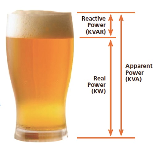
Apparent Power (KVA) is the vector sum of Real Power (KW) and Reactive Power (KVAR) and is the total power supplied through the power mains that is required to produce the relevant amount of real power for the load. Let’s look at a simple analogy in order to better understand these terms. 

Let’s say you’ve ordered a glass of your favourite beer. The thirst quenching portion of your beer is represented by Real Power (KW). Unfortunately, along with your ale comes a little bit of foam that doesn’t quench your thirst, represented by Reactive Power (KVAR). The total contents of your glass (KVA) is this summation of KW (the beer) and KVAR (the foam). The power factor is the ratio between Real Power and Apparent Power. It’s expressed as a value between -1 and 1 and can be either inductive (lagging) or capacitive (leading). If the power factor is 1, then all of the power supplied is being used for productive work and this is called ‘unity’.

Therefore, for a given power supply (KVA):

  • The more foam you have (the higher the percentage of KVAR), the lower your ratio of KW (beer) to KVA (beer plus foam). Thus, the poorer your power factor.
  • The less foam you have (the lower the percentage of KVAR), the higher your ratio of KW (beer) to KVA (beer plus foam) and the better your power factor. As your foam (or KVAR) approaches zero, your power factor approaches 1.0 (unity).


A power factor of -0.7 for example, indicates that only 70% of power supplied to your business is being used effectively and 30% is being wasted. The wasted power is the Reactive power (the foam in the previous example). Most loads are inductive in nature, which means the power factor will typically be less than unity. The further the power factor is from unity, the greater the apparent power drawn and therefore, the greater the current draw for the system.

The increased current may require an increase in the size of your transformers and installation power wiring. Increased current also results in increased heat which affects the longevity and lifespan of an electrical system. This can add a great deal of cost to the installation and may also limit the expansion of a plant.

It’s important because you may be paying for reactive power (foam) that you cannot use to power equipment. If you can reduce the foam, you can get more ‘beer for your buck’. Improving the power factor results in less current being drawn, therefore less electricity costs, less heat and greater longevity of the electrical system.

Many power suppliers charge for the base load (kW) and a maximum demand tariff. If this maximum demand tariff is measured in kVA, then improving the power factor reduces the kVA of

the installation, thus reduces the maximum demand tariff and thereby reducing your power costs.

It is actually a network regulation that customers maintain a specific minimum power factor (values depend on your region). Utility companies may charge customers a penalty on top of consumption charges when customer power factor is less than a determined value.

Poor Power Factor can be improved by installing Power Factor Correction (PFC) equipment. Traditional solutions incorporate banks of capacitors that work as silent reactive power ‘generators’, often housed in a metal cabinet similar to the one that houses your electrical switchboard. Fuseco offers the latest generation of advanced performance PFC solutions that do not need a capacitor bank and offer many advantages due to their compact and modular configuration.

An electrical load with a poor power factor draws more current than a load with an improved power factor for the same amount of useful power transferred and can put unnecessary strain on the electricity distribution network. By improving your power factor, you can reduce your electricity bills through lower monthly demand and capacity charges. Typically payback periods for power factor correction are between 1-3 years. Given the life expectancy of power factor correction equipment and the potential savings, it can be a very worthwhile investment. Poor power factor may cause power losses and voltage drops, which can contribute to overheating and failure of motors and other equipment. If your electrical system is near capacity, installation of power factor correction equipment may help avoid costly infrastructure upgrades by lowering the existing electrical demand on your system and improving efficiency stability.

Due to the operational temperature and safety requirements applicable to capacitor banks, traditional PFC systems are constructed as a separate, stand-alone assembly or in self-contained spaces within the overall construction of the main switch board. This results in the common situation where PFC systems occupy a large space, often taking up valuable floor space in switch rooms.

Sinexcel have applied new generation thinking and innovative design principles to create a new generation of PFC solutions that do not use a switched capacitor bank system. This has redefined what is possible from a cost vs performance vs space perspective.

Sinexcel SVG are a modular design that are available in wall-mount, rack-mount and rack/cabinet configurations. This flexibility gives engineers multiple options to cater for all situations and ultimately save valuable space and floor real-estate.

Compensating kVAr Capability vs Space

  • Up to 100kVAr capability from a wall-mount solution
  • Up to 100kVAr capability from a single rack-mount module
  • Up to 400kVAr capability from a single standard cabinet solution
  • Up to 600kVAr capability from a single ‘drawer-type’ cabinet solution

Related Resources

Located near Derrimut, Melbourne is a bottling & distribution facility of the timeless classic brand Campari. The electrical engineering team on site suspected that they had poor power factor, a fact that was confirmed once they conducted their power quality measurements. They calculated that a 350kVAr solution would be required and reached out to Fuseco for advice. The installation of a Sinexcel SVG system transformed their electrical environment.
Early focus on the various Power Quality topologies when putting together power engineering designs can have a huge impact on project performance, capital expenses and ongoing operational costs for the end users.
Harmonic resonance is a common problem that occurs when Power Factor Correction capacitors are installed into a system that is harmonically rich and most of the load is non-linear.
We are excited to announce the release of the new Sinexcel 200kVAr Static Var Generator (SVG) module!
Power Factor is a measure of how effectively incoming power is used in your electrical system (energy efficiency) and is defined as the ratio of Real (working) power to Apparent (total) power. By improving your power factor, you can reduce your electricity costs. Fuseco is Australia's leading experts in Power Factor Correction. Contact us for a free site appraisal and no obligation assessment.
By installing Power Factor Correction equipment, you will be able to improve your Power Factor and reduce your Peak kVA Demand Tariff and this will result in significant savings in your electricity costs. Fuseco is Australia's leading experts in Power Factor Correction. Contact us for a free site appraisal and no obligation assessment.
The Electricity Utilities are changing the way they billing you. Improving your power factor can result in considerable savings on your power bills. Fuseco is Australia's leading experts in Power Factor Correction. Contact us for a free site appraisal and no obligation assessment.

From the moment the AHF and SVG units were turned on our power factor issues were a thing of the past. At both sites our PF is now 0.99 on all phases all the time, the units react instantaneously to our fluctuating load and power factor and the result has been an excellent return on investment.

Brad Kilner

OPERATIONS MANAGER AT KILNER'S ENGINEERING

The PFC units are now installed and running. They are doing a great job at maintaining a constant PF of 0.99 across all phases. Great product and excellent support from both of you. Very pleased doing business with you. Your help has been much appreciated.

Darren Brownscombe

ENGINEER AT TURBOSMART

Technical Support

Our experts are all pre-eminent leaders in electrical products who provide excellent support in their areas of expertise.

Technical support

Talk to an expert

Our friendly team are highly trained product experts who really enjoy helping customers find what they need.

1300 387 326

call 1300 387 326

Enquire by email

We promise to respond within 4 business hours (AEST) or you will receive $100 off your next purchase.

Enquire now